

Why do TTGPs work sometimes and fail dismally at other times? More specifically, what laws of physics govern this operation and how can we make sure that we use them to our advantage?
Obviously there are instances where a TTGP does not work out as expected. And it may be that it was not good candidate in the first place. Or poor practices were used. Let's look at what is the necessary criteria for a good TTGP candidate and review the best practices. Also we will look at what are some of the "job killers" that may get overlooked.
Let's begin with a review the equations that apply to in-flow regions of the completion. The in-flow region is taken to be flow through the reservoir, into the perforations and on to the inside of the TTGP screen. We will not consider the outflow region which is from the inside of the screen and up the tubing. Flow up the tubing is governed by the rules for 3-phase fluid flow in vertical piping. And that's another subject that calls for a separate detailed study. So let's take a look at how the fluid gets from the reservoir and into the screen.
Shown here are two flow regions: the Radial Flow Region and the Linear flow region. For purposes of comparison, the units in each model are oilfield standard units, but as you will see, it is the absolute value of the ratio between some of these terms that dictate flow capacity. Therefore the units actually cancel out and are not shown here.
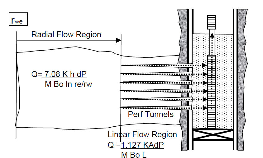
Note that the boundary for rw (radius of the wellbore) is not shown in this drawing either. This is because the term (rw) is only used in the Radial Flow Region equation and it really makes little or no difference whether we choose the end of the perforation tunnel or the outer edge of the original hole size as representing rw. The reason for that is that the ratio of re/rw is subjected to the natural log function (ln) in the denominator of the Radial Flow equation and the final number will always between about 7.1 and 7.8 when using a reasonable rw in non-frack situations. Fracking to increase rw by several magnitudes will obviously lower the ln(re/rw) term and result in much higher flow rates. But that is not the case here.
What this means is that production from Radial Flow Region of this system is primarily a function of K, h, and dP (all in the numerator), since the entire denominator is pretty much a constant after the well is drilled and the casing is cemented. But after the well is cemented, K and h become constants in this system. So the amount of flow coming from the Radial Flow Region and being delivered to the Linear Flow Region is almost purely a function of how much pressure drop we can efficiently deliver at the outer end of the perforation tunnel. In other words, we should strive to have minimal pressure drop in the adjacent Linear Flow Region. Therefore, the Linear Flow Region becomes the critical area where we have the most control over the factors that affect pressure drop in the perforation tunnels.
How can we best "save" the effects of pressure drop being by opening the well at the surface, instead of "wasting" this pressure drop in the Linear Flow Region? The obvious answer is that we will want a highly efficient Linear Flow Region.
Examining the Linear Flow equation, there are several variables that can be manipulated to yield a favorable draw-down to the outer Radial Flow Region. In the denominator Linear equation, we see that M and Bo will remain as constants during production. That is to say, unless we fall below the bubble point within the perforation tunnel - which would introduce what's know as "a phase behavior skin factor". But for our purposes, let's assume single phase flow - oil. In doing so, that only leaves "L" in the denominator which is inversely proportional to Q. i.e., the smaller that L becomes, the larger that Q will be. Hold that thought for a second.

In the numerator of the Linear Flow Equation we find that Q will be directly proportional to K and A.
If we put these three ideas together, then we would prefer to shoot short and fat perforations that will minimize L and maximize A. And we will want to pack that tunnel with the largest K proppant possible. i.e., high quality well sorted gravel pack sand with minimal residual fines or gel remnants.
But what happens if a perforated interval is not packed and the formation sand is allowed to fill the tunnels up to the screen OD? This is the worst possible outcome for a gravel pack and will generally result in a completion that yields little or no inflow or even burns a hole in the screen. Usually 10 - 15 bpd is all that's yielded. Why? By letting the formation sand fill the perf tunnel we have effectively taken a 300 md formation sand (arbitrary but common formation permeability) and put it in place of the 180,000 md gravel pack sand that we hoped would occupy the perforation. And by doing so we have cut the capacity of the Linear Flow Region to 1/600th of it optimal capacity had the gravel pack sand been in its place. (300/180,000)
It should be apparent by now that the success or our gravel pack, be it a large bore or a thru-tubing pack, will depend almost solely on how effectively we can fill every perforation tunnel with high-perm proppant. Here is a summary of some best practices that will help to optimize every thru-tubing gravel pack completion.
- Absolutely, clear fluids is the number one priority of any gravel pack. More specifically, 17 - 20 ntu fluid with HEC gels for viscosifier when necessary. No solids, such as calcium carbonate, should be allowed into the system. Surface tanks should be spotless and a dual pod filter system should be used for switching and cleaning on the fly. Since a TTGP is generally a plug-back operation, there are generally no issues with pipe dope. But if we were are considering a primary large-bore gravel pack we would strive to minimize pipe dope by using a paint brush on the pin end only for the final pipe trip in the hole. Since doping pipe with a dope brush is a second-nature action for the floor hand, it is best to remove the dope brush from the floor for the final workstring run. And plan to pickle the pipe with an acid/solvent flush to remove rust and pipe dope remnants.
- Shoot large diameter, short holes. Sacrificing diameter to shoot deep penetrating holes is not generally called for unless there is a hole washout problem on the caliper log. Nodal analysis has revealed that 12 spf is far better than 6 spf, but 18 spf begins to yield diminishing returns. So 12 spf with big hole (BH) charges is generally taken as optimal.
- Shoot decentralized hollow steel carrier guns to minimize both stand off from the casing and gun debris. Every hole will have a low side at depth and we much be sure that the gun lays against the casing when shot. Shooting a multi-phase gun that fires in a 90 or 60 degree pattern is ineffective. The preferred phasing is a 45-0-45 pattern. Again, all big holes. A circular phasing pattern defeats the purpose of minimizing standoff and maximizing A.
- The following is a consideration for thru-tubing gravel packing only. A large bore rig pack will have completely different considerations. Once the first set of holes is shot overbalance, then it is crucial that the formation sand NOT be allowed to fill the perfs by allowing the well to flow. The way this is best done is to have a dedicated pump operator who will "roll the pumps" at minimal speed and keep filtered completion fluid going into the holes at all times until the gravel pack is finished. By allowing the hole to equalize with the formation, sand will fall into the perfs and even into the casing. So believe it or not, the pump hand is one of the most important components to a successful pack. This is critical and can ruin the whole job in a blink of the eye. The length of time required for slow pumping can be anywhere from 12 - 36 hrs of constant perforating and deploying the screen assembly. So make sure that a tag team is assigned this job to assure zero breaks in the operation to allow bathroom and galley breaks. Again, if the pump is stopped for any reason and the well is allowed to equalize with the formation pressure, sand will enter the perforations and the entire job will be compromised.
- Based on number 3. above, it is always best to conduct the thru-tubing gravel pack as a 24 hr operation. Read this sentence again.
So, getting back to the opening question, what constitutes a good candidate for TTGP?
First of all, a good TTGP candidate will need to be a reservoir of sufficient size to support a 24 hr operation either on lift boat or platform. 24 hour operations can sometimes be a limiting factor on an unmanned platform in water that's too deep for a L/B operation. In such a case, the perforation runs and the screen deployment will need to be scheduled to be completed in one day and still leave enough time to pump a "sized slurry" of recommended sand sieve that will cover the perforations before shutting down. This can prove to be a lot for one day, so obviously such an operation will not stand for a long perforated interval that requires multiple gun runs on a daylight operation. Two gun runs, a screen run and an over-the-top batch mix will be a full day's work and will likely run long on time. So make preparations for that day by securing a dedicated crew boat or even a sleeper boat. Obviously all hands on a job like this will need to be sea worthy.
One final note: If the reserves are deemed too small to support anything but a full blown lift boat or boat assisted operation, then the zone may not be a candidate. Short cutting the TTGP process by perforating and hanging a screen off with no sand pack is a sure recipe for disaster. Typically the screen will burn out when the formation sand comes in which results in sanded up tubing, cut out tree valves and sanded up facilities. And lastly, if such a "hang off job" does work, then you probably didn't need a screen in the first place. It's just not worth the risk. Do it 100% or expect a failure.
Post script question: Why do we see open-hole screens work with no sand pack?
Answer: Because in an open hole screen completion, the fluids are in radial flow all the way to the screen.There are no perforations and there is no linear flow regime. The primary concern for open hole completions is to run a screen that will allow the mud cake (generally a fine grind calcium carbonate) to flow off the sand face and through the screen, yet still be small enough to hold back the formation sand. And again, this requires an expensive premium screen, not a keystone wire wrap. So don't scrimp on dollars for the screen in a horizontal open-hole completion.It's just not worth it.
Is your company in need of engineers, consultants, or operators? Stokes & Spiehler has been in business for 45 years placing Consultants on Operator’s drilling, completion, and workover projects. We also supply engineers, rig clerks, mud engineers, regulatory agents, and others. In addition, we offer qualified personnel for project management, engineering, and field consultants.